
Reading Punched Paper Tape
Just before we started ‘A’-level Computer Science, our school was provided with a TeleType ASR 33 that looked something like this one which is at the National Museum of Computing:

and an acoustic coupler, made by Modular Technologies, that we could use to connect to the local college’s ICL 2903 BASIC system. Here’s one, also at the National Museum of Computing:
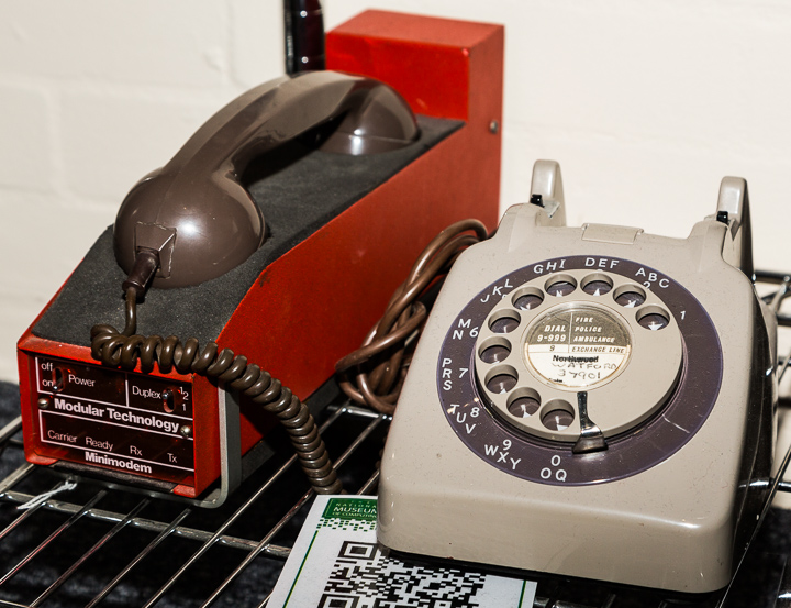
Using this connection, we could develop the BASIC programs that would form part the coursework submitted as part of the examination. As you can see, on the left of the TeleType is a mechanical paper tape punch which would punch on paper tape exactly the same text that was being printed out so to save our programs off-line, we would turn the punch on and then list the program.
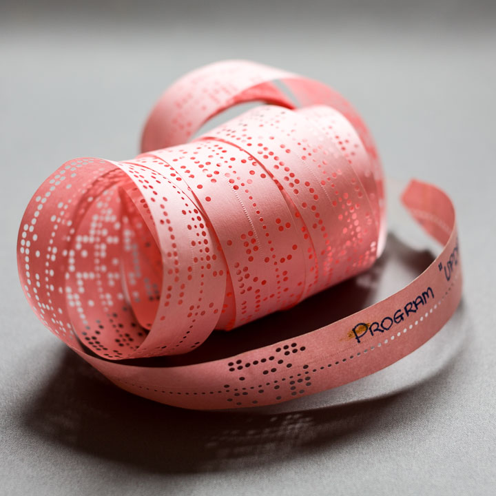
I still have some of these punched paper tapes and so I thought it would be interesting to recover them forty years later and see if they would still run on an emulator I am developing for the ICL 2903 Interactive BASIC System. Here’s the paper tape for one of my smaller programs:
How Data Is Represented
If we take a closer look at part of the tape we can see that in each row of data (called a frame), there are spaces for nine holes, eight holding data and one row of smaller sprocket holes:
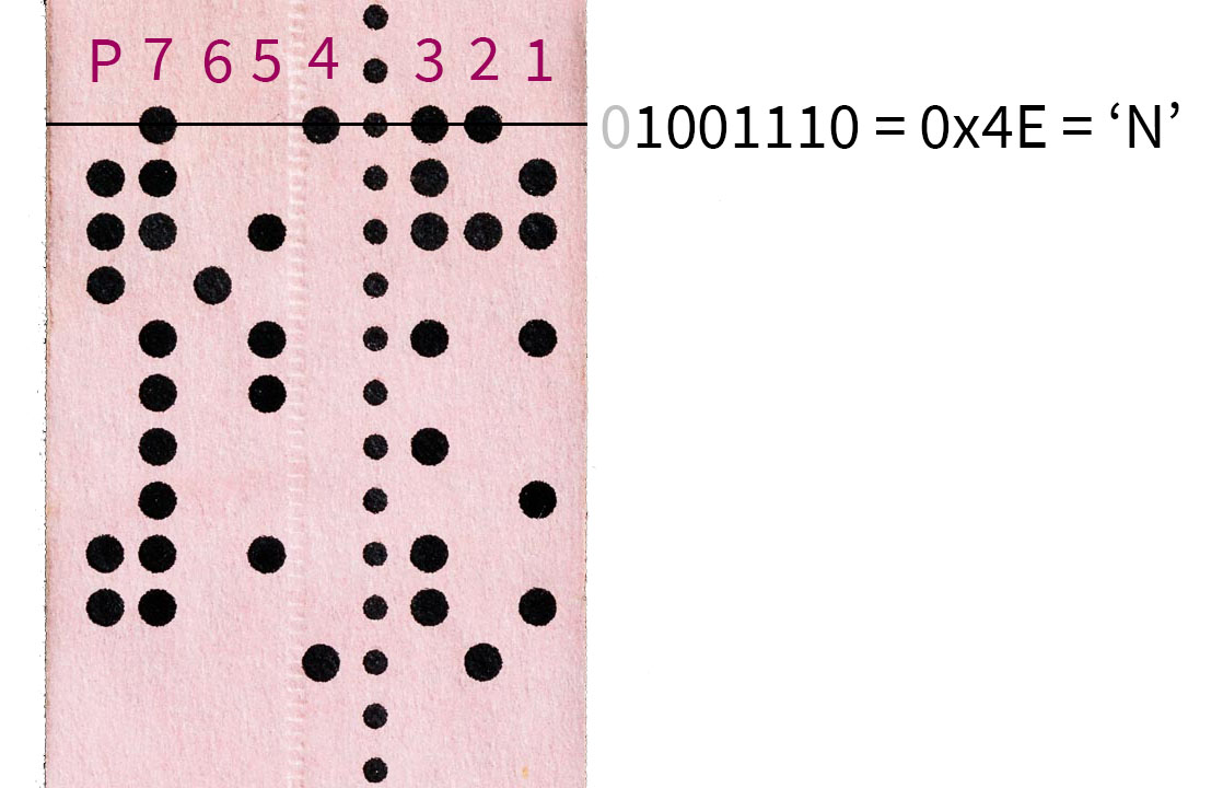
The eight data columns consist of one parity bit and seven bits holding the character code of the character each row represents: a hole is a binary ‘1’ and a missing hole is binary ‘0’. THe most significant bit of the code is held in the column I’ve labelled 7 and the least significant bit is in column 1. Hence, ignoring the parity column, the row indicated holds the seven data bits 1001110 which is 0x4E in hexadecimal. This is the ASCII character code for the character ‘N’.
The left-most column, labelled P, is the parity bit. Parity bits are used to provide a small amount of error checking by imposing the rule that the total number of data holes in each row must be even. In this case, columns 1..7 contain four holes and four is already even, so no parity hole is needed. The row below it has three holes in columns 1..7 so an extra hole is added in the parity column. When the tape is being read, if it reads an odd number of holes, the reader knows something has gone wrong.
The ICL 2903 system has its own system of character codes defining sixty four characters. The first thing the system needs to do when reading the paper tape is to convert the ASCII codes into its own internal equivalent.
Two values have a special meaning: 0, which is no holes, is not considered to be a character. This means that we can run out blank tape between characters with no effect. The value 128, which is eight holes (including the parity hole), is also ignored. This means that if we make a mistake when preparing the paper tape we can back up one position and delete it by punching through all of the holes.
If you decode the remaining frames in the piece of tape shown, you will end up with the text NEW UPDATE followed by a line-feed character, 0x0A, which marks the end of the line. This then is a command to the BASIC system telling it to clear any program it has previously loaded so we can start to enter a new one and that the new program’s name is to be UPDATE.
What are the Sprocket Holes For?
You’ll notice that there’s a row of holes running down the tape between data columns 3 and 4. These are obviously sprocket holes that are used by the reader to feed the paper tape through the reading position but this isn’t their only purpose.
The sprocket holes are smaller than the data holes and the centre of each sprocket hole lines up the the centre of the data holes. This is used by the reader to detect when it’s time to read the data: when the reader detects the small sprocket hole, then the large data holes are safely in position to be read.
This means the paper tape is self-clocking - the speed at which it is physically drawn through the reader can vary freely while it is being read because the sprockets provide a “tick” telling the reader when the next frame is in position.
Building a Paper Tape Reader
There aren’t many punched paper tape readers around these days outside of museums so I thought I might try making something myself that would last just long enough to read my tapes.
The first thing we need is to be able to recognise the difference between a hole and a space. There are three ways of doing this:
Mechanically: have spring-loaded pins that pop up when a hole passes over them but are forced down when there isn’t one. This is slow but the TeleType reader works like this because it only has to read at ten characters per second
Electromechanically: use conducting brushes on one side and a metal plate on the other. The paper prevents them making an electrical circuit when there’s a space but when there’s a hole, they connect and current flows.
Optically: use a light detector on one side of the tape and a light source on the other. More light passes through when there’s a hole between them and electronic components detect the change.
The first two are ruled out by my woefully poor mechanical engineering skills, so that leaves me with the optical option.
I bought some photodiodes, resistors and a breadboard along with an Arduino (a small system used by hobbyists for projects just like this). The photodiodes can detect the changing light levels - the more light, the more current they generate. The resistors are needed to limit the total amount of current flowing through the circuit to protect the photodiodes from burning out.
As an experiment, I connected a photodiode to the Arduino’s GND pin and one of its analogue I/O pins with a resistor in parallel with the photodiode and then ran an Arduino script to read the I/O pin level and send it up the serial line to the PC controlling the Arduino. This setup could reliably detect the difference between paper and hole and revealed that the photodiode was responsive enough to suggest it could read tape at a speed of the order of ten metres a second. My plan was to take advantage of the self-clocking nature of the tape and pull it through my reader by hand - ten metres a second is far faster than I could pull the tape without risking tearing it.
The next step was to build a little housing to hold the photodiodes and paper tape in position. I glued some scrap plastic sheets together to make a thick block of plastic and then drilled holes in it to hold the photodiodes below its surface. On top of these I added a thin sheet of plastic with smaller holes drilled in it so that the photodiodes only saw light from a small area over their centre.
Nine photodiodes are needed - eight for the data and one for the sprocket “clock” - but alas, the photodiodes were too large to fit side by side along one row so I had to stagger them:

This means that when the Arduino samples all of the photodiodes, it reads bit 8 of frame 1, bit 7 of frame 2 and so on down to bit 1 of frame 8. The next time, it will read bit 8 of frame 2, 6 of frame 3 down to bit 2 of frame 8 and bit 1 of frame 9. Only after reading eight frames will we have all of the bits of frame eight. From that point on, each new frame read completes the next frame.
Because of this, the reading software will have to keep track of which bits of which frames have been received and output frames as they are completed.
I decided to keep the Arduino script as simple and as fast as possible. All it does is read the raw levels of the nine analogue I/O pins and sends the results up the serial line to the controlling PC. Software running on the PC then inspects the level of the sprocket clock’s pin to detect when it is below a hole and so the other data pins are ready to process. It then converts their levels into hole/space values and reassembles each frame’s bits in turn.
Having got it all working, all that remained was for me to uncoil each roll of paper tape for the first time in nearly forty years, set the software running and pull the tape through the device. I erred on the side of caution and pulled at around a metre per second. This is a data rate of about 400 frames a second.
Here’s the device in all its glory ready for use supported on some books for stability:

It’s rather Heath-Robinson in appearance and please don’t laugh too much at my soldering skills - it’s the first time I’ve done any electronics at all other than a few exercises with 7400-series logic chips and a breadboard one week at college. Just be as astonished as I was that it worked to do the job it was designed to do and no more.
Finally, for completeness, here’s what was on the paper tape you saw at the top of this article. It turns out to be part of a suite of programs I wrote to deal with the distribution of examination results to pupils. THis program is a fairly traditional batch update of an input data set inserting, deleting and replacing records to generate a new output data set:
100 REM :  UPDATE CANDIDATE FILE WITH SORTED AMENDMENTS
110 PRINT "FILE UPDATE ";DAT$;LIN$(2);"FILE TO BE UPDATED ";
120 INPUT U$
130 PRINT "NEW FILE ";
140 INPUT N$
150 REM :  FIND FILES , SET LAST RECORD TO NULL , SET FLAG
160 FILE #1:U$
170 FILE #2:N$
180 R$="0000"
190 F=1
200 REM :  INPUT AMENDMENT
210 INPUT T$,A$
220 T$=SEG$(T$,1,3)
230 IF T$ = "END" THEN 640
240 REM :  CHECK THAT RECORD HAS NOT ALREADY BEEN OUTPUT
250 IF A$ >= R$ THEN 280
260 PRINT "OUT OF SEQUENCE . AMENDMENT IGNORED ."
270 GOTO 200
280 REM :  BRANCH TO RELEVENT UPDATING ROUTINE
290 IF T$ = "DEL" THEN 340
300 IF T$ = "INS" THEN 430
310 IF T$ = "CHA" THEN 540
320 PRINT "DELETE,CHANGE,INSERT OR END ONLY . AMENDMENT IGNORED ."
330 GOTO 200
340 REM :  DELETE RECORD FROM FILE BY SETTING OUTPUT FLAG TO 1
350 IF A$ = R$ THEN 190
360 IF F=0 WRITE #2:R$
370 READ #1:R$
380 F=0!REM RESET FLAG ON EACH NEW INPUT
390 IF R$#"\\\\" THEN 350
400 PRINT "RECORD UNKNOWN . FILE END REACHED . RUN ABANDONND ."
420 STOP
430 REM :  INSERT NEW RECORD IN FILE
440 IF A$ < R$ THEN 520
450 IF A$#R$ THEN 480
460 PRINT "DUPLICATE ENTRY . AMENDMENT IGNORED ."
470 GOTO 200
480 IF F=0 WRITE #2:R$
490 READ #1:R$
500 F=0
510 GOTO 440
520 WRITE #2:A$
530 GOTO 200
540 REM :  CHANGE EXISTING RECORD
550 IF R$ = "\\\\" THEN 400
560 IF A$ = R$ THEN 610
570 IF F=0 WRITE #2:R$
580 READ #1:R$
590 F=0
600 GOTO 550
610 PRINT "NEW RECORD ";
620 INPUT R$
630 GOTO 200
640 REM :  END PROCEDURE
650 IF F=0 WRITE #2:R$
660 IF R$ = "\\\\" STOP
670 READ #1:R$
680 WRITE #2:R$
690 GOTO 660
999 END
To be sure, it’s not the greatest program I ever wrote but bear in mind that the code we wrote as part of the course was aimed at learning something, not developing correct, maintainable software. On the plus side, it does avoid what was claimed to be the commonest bug in data processing applications: reaching the end of one data stream and forgetting to copy the rest of the other to the output.